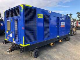
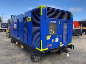
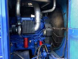
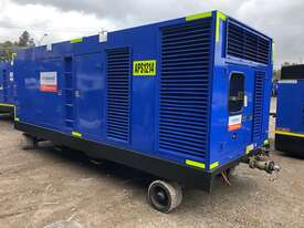
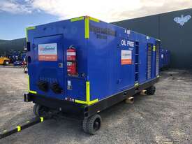
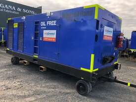
1500cfm Diesel Oil Free Air Compressor
Up to 150psi
Built in after cooler
GENERAL INFORMATION AND OPERATIONAL
THEORY
General
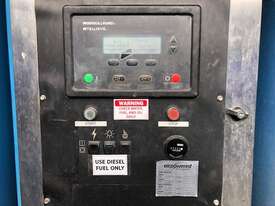
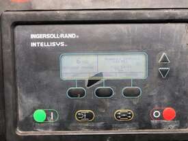
The NHP1500 machine has and electronic monitor
and control system to provide discharge air pressure
control and engine and package monitor functions.
The system uses the INTELLISYS controller to
perform these functions. The electrical system
connects all the necessary switches, sensors and
transducers to the INTELLISYS controller in order for it
to perform the monitor and control functions.
INTELLISYS Controller
The INTELLISYS controller is the heart of the
NHP1500 machine monitor and control system. It
provides data collection, alarming and control
functions for compressor operations. It is an Intel
microcontroller based unit with analog and digital
inputs and outputs.
The first function of the INTELLISYS controller is to
scan all analog and digital inputs at a given time
interval. The analog and digital inputs are scanned
every 100 milliseconds. The analog values are then
compared againstminimum and maximumvalues and
an ALERT or SHUTDOWNis issued, if a value is out of
range. The various ALERTS and SHUTDOWNS are
listed in Section 10 of this manual.
The second function of the INTELLISYScontroller is to
control air discharge pressure based on machine
demand. The INTELLISYS controller monitors
machine discharge air pressure, PT4, and varies the
engine speed to maintain the discharge air pressure at
the desired setpoint.
The third function of the INTELLISYS controller is to
communicate with the diesel engine via the J1939
CAN network. The INTELLISYS controller can read
various engine parameters and diagnostic
information. The INTELLISYS controller provides the
engine throttle setting via the J1939 CAN on software
versions 2.0 and greater.
Software versions under 2.0 use the frequency throttle
to communicate with the engine. A square wave
frequency signal from 150 Hz to 375 Hz is sent from
the INTELLISYS controller to the engine controller.
The signal is a linear signal from 150 Hz at engine idle
(1200 RPM) to 375 Hz at maximum run speed (1800
RPM).
Figure 2--1 on page 5 shows the signal connections
from the INTELLISYS controller and the engine
controller.
Sensors and Transducers
The electronics system contains sensors and
transducers that are used to collect data from the
compressor. There are two types of temperature
sensors, RTD’s and thermistors. Both of these
devices exhibit a change in resistance as the
temperature changes. The resistance causes an input
voltage change to the INTELLISYS controller input
and is interpreted as a temperature change. These
temperature probes look similar, but have different
connectors. They are not interchangeable.
The electronics system also uses pressure
transducers to measure compressor pressure
changes. These devices have an output signal of .45
VDC to 4.5 VDC, corresponding to 0 psi and the
maximum measured psi for a particular device. The
maximum pressure transducer ranges are 15, 100 or
225 psi. The 0 --15 psi is a vacuum transducer and the
100 and 225 are gauge pressure devices. These
transducers are provided with 5 VDC excitation to
power the device. There are three wire devices:
excitation, signal and ground.
Digital Inputs and Outputs
The INTELLISYS controller scans digital inputs such
as switch contacts. These are either “ON” (24 VDC) or
“OFF” (0 VDC). They are devices such as the
emergency stop button and Auto Start contact.


 Facebook
 Twitter
 Email a Friend
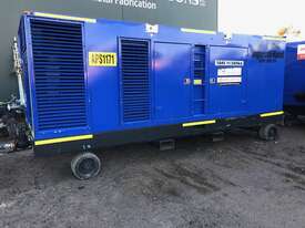


 Print
Print